The accurate calculation of the burning surface area in the solid rocket motor column combustion process has always played an important role in the design of solid rocket motors. Domestic and foreign scholars have also proposed many calculation methods, such as general coordinate method, finite element method and boundary coordinate method. However, these methods are basically numerical methods, and their input is complicated, and it is impossible to display the precise change of the burning surface during the combustion process, the calculation accuracy is not high and the burning surface fluctuation is easy to occur. With the rapid development of computer hardware and software, especially the development of general-purpose CAD software, many new methods based on graphics processing are provided to solve this problem.
Pro/ENGINEER is a new generation of CAD/CAE/CAM software introduced by PTC in the United States. It has features based on features, full parameters, full correlation, and a single database. Since its launch, due to its powerful features, it has quickly gained popularity among the industry and quickly became one of the most popular CAD software in the world today. In addition to the above advantages, Pro/ENGINEER provides a complete secondary development interface, enabling users to develop custom application software for various industries based on the Pro/ENGINEER platform. This article is based on this development of solid rocket engine charge CAD software. In the software development, the secondary development kits Pro/Toolkit and Vc++6.0 provided by Pro/ENGINEER 2001 are used as tools to make full use of the powerful 3D modeling functions and parameterization features of Pro/ENGINEER.
2 Software design principles and functions
2.1 menu design
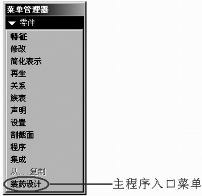
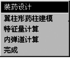
Since the functions of the software are all done in the part drawing mode, the software adopts the mode menu as shown in Figure 1 and 2.
2.2 Automatic Modeling
The reason why the software should provide the automatic modeling module is to improve the modeling speed of the medicine column, and on the other hand, because the software has to realize the function of changing the burning surface, there are some restrictions on the drawing method, and the automatic modeling program is utilized. It can fully meet the needs of changing the burning surface.
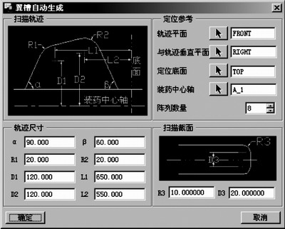
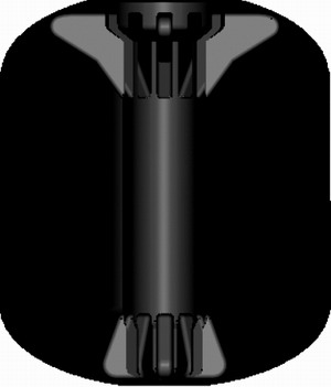
Pro/Toolkit provides three methods for program modeling: feature description, cluster table, UDF, and literature 1. These three methods are described in detail. The software uses a relatively simple UDF method. The wing-shaped column is generally composed of The outer contour, the inner hole, the wing and the groove are formed. The outer contour is formed by the rotating features of the added material, the inner hole is a hole feature, the wing is a scanning feature, and the groove is a rotating feature of the shear material. These features are pre-built and the reference datum, variable size, and variable size symbols are defined, and then saved as a file with the suffix gph. The drug column model is automatically generated by calling these files through the program and reassigning the variable size and reference datum. Figure 3 is an automatic modeling window for a type of wing, and Figure 4 is a final drug column model built using an automated modeling program.

Figure 1 main menu entrance

Figure 2 software main menu

Figure 3 wing automatic modeling window

Figure 4 A drug column model built using an automated modeling program
Next page
include the golves:PVC gloves industry gloves
helmets
galoshes safety shoes
safety goggles
jackets
Labor Products,Latex Household Gloves,Rubber Rain Boots,Leather Safety Shoes
SHANGQIU DING LIAN INTERNATIONAL TRADE CO. ,LTD , https://www.dingqitools.com