(1) Common base part of the fixture: 1 body, 1 drill template, 3 bushings and other standard components.
(2) Adjustable parts of the clamp: 2 pieces of V-shaped block and baffle, 1 piece of column support, 7 pieces of drill sleeve, 1 piece of spacer, 1 piece of eccentric fitting and pressure plate, 1 piece of adjustment pad, straight directional plate 1 piece, 1 piece of curved plate orientation plate, 9 positioning shafts, 10 positioning pins, 5 angle plates, 1 positioning block, 6 orientation keys and 3 positioning keys. Other drill sleeves, orientation keys, positioning keys and other components are selected according to the factory standard or national standard.
4. Universal base, key adjustable component structure design
(1) Universal substrate
The drill template is fastened to the body through the positioning pin, and the three holes of the template are drilled and the bushing is installed to ensure that the hole is centered on the V block by d 0.02 mm.
The three holes of the drill template are used to expand the drilling position and clamping space of different products. This approach ensures that the key components of the fixture have the rigidity, precision and service life of a dedicated fixture.
(2) Composite adjustment components (V-shaped block, baffle, positioning block)
Two different sizes of V-shaped blocks (suitable for shaft diameter d16.3 and below and d22 or more) are slidably coupled with the body T-shaped groove through the positioning key, through the concave groove and the positioning block, and are combined with the baffle to form a composite Modulation components. The positioning error of the combined mode is relatively small, and in the actual machining process, the clamping force and the cutting force portion of the workpiece can cancel each other, and the displacement error after the force between the components can be reduced.
Move the V-shaped block during installation adjustment, ensure the distance from the center of the concave groove to the drill template, or adjust the baffle positioning screw to ensure the distance from the end face of the shaft to the drill template.
(3) Angle board
Installation method: According to the positioning angle requirement of the workpiece, the angle plate and the orientation plate are selected, and the orientation key is connected with the positioning block and the orientation plate.
Working principle: The orientation plate is slid or fixed on the angle plate by the orientation key to ensure the angle requirement of the workpiece positioning groove or hole. Achieve the positioning angle.
(4) Straight directional plate
Installation method: According to the positioning requirements of the workpiece slot or hole, select the positioning axis or positioning column and connect with the positioning block or angle plate through the orientation key.
Working principle: Fix the workpiece groove or hole by fixing or sliding the orientation plate on the positioning block or the angle plate. When positioning the groove, the positioning column is selected to meet the requirements of 7 kinds of positioning; when positioning the hole, the positioning axis is selected to meet the three positioning requirements.
5. 11 kinds of fixture positioning methods
According to the different process positioning requirements of the workpiece, the clamp positioning mechanism can realize 11 kinds of positioning modes by changing the clamp angle plate and the positioning block and moving the V-shaped block and the pressure plate position to achieve the ideal fixture mode.
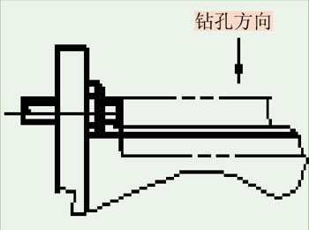
(1) Positioning of the axial end face of the workpiece (see Figure 7)

Figure 7 Workpiece axial end face positioning
Previous Next
Kn95 Mask,Kn95 3D Mask,Kn95 Face Mask,Kn95 Respirator
Ningbo Autrends Prevention Products Co., Ltd , https://www.autrendsafety.com