Abstract: This paper mainly introduces the application, process control and solution measures of energy storage welding machine in the field of microelectronic packaging.
Key words: packaging; energy storage welding; capacitor; application
1 Introduction
With the increasing miniaturization and multi-functionality of electronic equipment, users have higher and higher requirements for the reliability of hybrid integrated circuits. If there is no good and reliable package to protect the various components of the hybrid integrated circuit, the hybrid integrated circuit will It is affected by the external environment and even causes the complete failure of the circuit. The integrated circuit package is to place one or more integrated circuit chips with certain functions in a suitable outer casing container to provide a stable and reliable working environment for the chip. As the main form of hybrid integrated circuit package, energy storage soldering is suitable for hermetic packaging of small and medium cavity and high reliability hybrid integrated circuits. The working principle, process control and solution measures of the energy storage welder are discussed below.
2 The working principle of the energy storage welder
Put the metal cap and the tube seat in the upper and lower welding molds of the corresponding specifications and apply a certain welding pressure, and use the energy stored in the storage capacitor for a long time to release the energy at the moment of welding. Features to obtain a very large welding current, the contact resistance converts electrical energy into thermal energy to achieve the welding process. The relationship between welding current and welding pressure is shown in Figure 1.
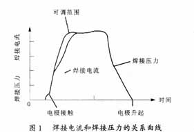
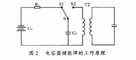
Figure 2 shows the working principle of capacitor energy storage welding with a welding transformer. When the switch S is turned to S1, the capacitor Cp is charged, and after Cp reaches the required voltage, S is further brought into contact with the point S2, and the capacitor Cp is discharged through the primary winding of the welding transformer T2. Resistor R1 controls the charging current and charging time. Since the resistance of the welding circuit is small, the current is large, and the instantaneous heat generated is large, which is convenient for welding.
3 characteristics of energy storage welder
The energy storage welder uses transistor components for program control. The charge and discharge switches use thyristors instead of bulky AC contactors and squibs. As a non-contact high-current switch, the thyristor has the characteristics of small size, no noise, and convenient use. In particular, its pressure drop is only 1/10 of the igniting tube, so that electricity can be effectively utilized. With the development of energy storage electrolytic capacitors, the energy storage type of the energy storage welder can be very large, and the volume is small. The charging voltage is precisely controlled by the electronic switch and continuously adjustable, and monitored by a voltmeter. The line is equipped with an overvoltage protection device to prevent breakdown of the energy storage capacitor.
Since the charging current of the capacitor energy storage welder is much smaller than the discharge current, its impact on the power grid is small, and the power supply power is not high. In addition, due to its extremely short discharge time, the performance of the welder can be stabilized in the case of fluctuations in the power supply voltage. Its discharge range does not have the cooling interval that occurs when the current is reversed in the AC circuit. Therefore, it is suitable for welding light metals with good electrical conductivity and thermal conductivity, such as low carbon steel, Kovar, stainless steel, nickel-chromium wire and other conductive materials. Metal with good thermal conductivity.
3.1 Capacitor energy storage welding energy
The energy of the capacitor is charged by the DC power supply. If the energy stored in the capacitor is represented by EK and the capacitance is represented by Cp, then EK can be obtained by (1):
![]()
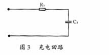
The storage energy of the capacitor is proportional to Cp and proportional to the square of the charging voltage Uc. To change the EK, Cp or Uc can be adjusted. In order to increase the energy stored in the capacitor, it is more effective to increase the charging voltage than to increase the capacity. To charge the capacitor, DC power is required. The rectifier circuit must be designed. As shown in Figure 3, if the energy at the output of the DC power supply is EC, the EC can be found by equation (2).
Austenitic Stainless Steel Ball(AISI304, 304L, 316, 316L)
Strong Anti-Rust Performance, Can Be In Direct Contact With Neutral Liquids. Special Bearings, Water Pumps, Valves, Aerosols, Dispensers, Food Machinery, Medical, Cosmetics And Other Fields.
Martensite Stainless Steel Balls(AISI420, 420C, 440, 440C)
Precision Bearings, Auto Parts, Bicycles, Mixers, Slide Rails, Conveyor Belts, Skateboards, Casters, Valves, Etc.

Stainless Steel Balls,Stainless Steel Bearings,Ss Bearing,Stainless Ball Bearings
CHANGZHOU HUARI STEEL BALL CO., LTD. , https://www.stwballs.com