It is well known that the cutting and grooving process has the same basic objective as ordinary turning operations, that is, the workpiece is machined to the desired shape to meet the accuracy requirements and maximize productivity. However, in addition to this, cutting and slotting applications have their own characteristics in terms of tool strength and stiffness as well as chip control. Tool manufacturers can only meet the special needs of cutting and grooving processes with innovative tool design and advanced coolant delivery strategies.
Tool design skills
As with normal turning operations, the cutting and grooving process also uses a stationary tool to cut the rotating workpiece . The first thing to consider is to configure the tool system to produce the desired workpiece shape. Therefore, the design of the cutting and grooving tool system varies depending on the size and depth of the workpiece. For example, for deep grooving and cutting on large workpieces, as well as shallow grooving and cutting on small workpieces, the tool manufacturer will provide cuts in a flat or vertical configuration that are directly clamped into the shank. Grooving blade.

X4 series tools for cutting and cutting small parts
An example of this is Seco's new range of star-shaped vertical design blades, which have four cutting edges and are therefore called the X4 series. With a cutting width between 0.5 mm and 3 mm (0.02" – 0.12"), this insert is designed to minimize material consumption during cutting and to accurately cut and simulate small and medium-sized complex workpieces. Shape processing. Depending on the width of the cutting edge, the maximum depth of cut of the tool is between 2.6mm and 6.5mm (0.10" to 0.26"), while the maximum diameter of the cuttable bar is between 5.2 and 13 mm (0.20" to 0.52"). between. The vertical design of the insert guides the cutting force to the shank for maximum rigidity, stability and productivity.
After determining the basic shape of the insert, the choice of the rake angle of the cutting edge is a key factor in the effectiveness of the cutting and cutting. The zero-degree rake tool allows vertical alignment with the workpiece and transfers cutting forces directly to the shank for improved accuracy, tool life and surface finish. However, after the cut is completed, the zero degree tool will leave small protrusions or pointed ends in the center of the cut bar. If you do not want to leave a protrusion, you should use a tool with a smaller rake angle to cut the protrusion as it passes through the center of the workpiece. In addition, in some workpiece materials, the rake cutter is less prone to burrs.
After setting the basic tool configuration, the material properties of the workpiece usually determine the blade model that is best suited to machine the workpiece. Blade materials that are difficult to machine or interrupted cutting should typically use blade types with higher strength and impact resistance, while highly abrasive workpieces require blade models designed for wear resistance.
Tool application recommendations
There are some specific setup suggestions for cutting and grooving tools. When installing the tool, care should be taken to make the blade perpendicular to the axis of the workpiece. This minimizes axial forces on the tool and prevents the sides of the friction blade. For the tool position, the center height of the cutting edge should be as close as possible to the center of the workpiece. The deviation should be within +/- 0.1 mm/0.004". This is also to prevent excessive pressure on the tool to avoid shortening the tool life.
Cutting parameters for cutting and grooving tools are different from normal turning. If the spindle speed is constant, the cutting speed will drop to zero when the tool is turned to the center of the bar. Slowing down can put heavy pressure on the tool and can cause the workpiece material to stick to the cutting edge. Therefore, the feed rate should be reduced (up to 75%) as the tool approaches the center of the part. In addition, the cutting speed can be adjusted to minimize vibration. The blades used in the cutting and grooving process are typically narrow blades, which tend to result in unstable cutting. Therefore, as far as possible, the blade is fixed in the shortest arbor and clamped in the thickest shank without interfering with the workpiece. These measures also help to control the vibration. Ensuring the stiffness of the machine itself, which is necessary in any machining operation, also helps to reduce unwanted vibrations.
Chip control problem
The cutting and grooving process is characterized by a very narrow cutting zone, which poses a problem for chip control during processing. Especially in the cutting process, the tool is surrounded by the workpiece material on both sides during cutting, which limits the discharge path of the chip. Finally, depending on the material of the workpiece, the thin chips generated during the cutting and grooving process are often not broken. Out-of-control ribbon swarf can cause chip clogging, damage to the workpiece and endanger the operator. Not only that, but chip control issues can also hinder the implementation of unattended or "fully automated" processing.
Many tools for cutting and grooving use a specially designed cutting edge groove to bend and break the chips. If surface roughness and other conditions permit, the tool feed (also called "parking") can be paused during cutting to help break the chips. Another method of chip control is to use coolant to flush out chips that may clog the cutting zone. However, conventional cast coolants typically do not produce sufficient pressure in the cutting and grooving applications to reach the cutting zone. Not only that, but the position of the pouring coolant nozzle is also difficult to determine, and the coolant cannot flow to the most needed part. Finally, the relatively weak casting coolant flow may be converted to steam in the cutting zone, which in effect creates a barrier that prevents the heat generated during the cutting process from escaping.
An alternative to pouring the coolant is to spray the coolant at a high pressure as close as possible to the cutting edge. Today's machine coolant pumps typically provide pressures from 20 bar (290 psi) to 70 bar (1015 psi). For example, Seco's coolant delivery systems offer a wide range of applicability, operating pressures down to 5 bar (72 psi) (possibly affecting productivity), up to 70 bar (1015 psi), and even up to 275 High pressure at bar (4351 psi).
For best results, the high pressure coolant must be delivered at a fixed point and as close as possible to the cutting zone. Tool manufacturers have developed numerous high pressure coolant delivery systems. A popular practice is to deliver coolant through a blade. However, the most efficient coolant flow creates a "wedge" between the cutting edge of the insert and the chip to lift and break the chips. Obviously, when the coolant is delivered through the blade, it is difficult to direct the flow to the optimum position and no wedges can be created. This is not enough to allow the coolant to enter the vicinity of the cutting zone. To form the wedge, the flow must be as close as possible to the cutting edge.
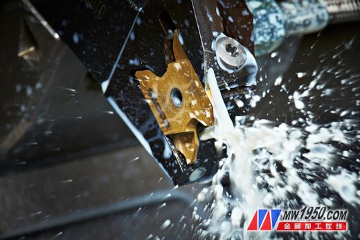
Jetstream Tooling's coolant delivery system provides fast guidance to high pressure coolant
As a result, Seco has developed a coolant delivery system called the Jetstream Tooling, which directs high pressure coolant through a deflector located in the shank. The small holes in the deflector create a violent high-speed coolant flow that penetrates and lubricates the high friction zone between the workpiece and the cutting edge of the tool. Recently, in an innovation aimed at controlling chips under difficult conditions, the company applied the technology called Jetstream Tooling Duo to the X4 cutting and grooving arbor. This method delivers coolant from two outlets. In addition to the upper nozzle that sprays the optimum machining point of the forward flank, the new Duo technology uses an additional coolant nozzle to flush the clearance surface. The cutting edge receives high pressure coolant from two opposite directions (upper and lower) to maximize chip flow and cool the cutting zone.
Specialized cutting points
Chip control is especially critical when machining difficult-to-machine workpiece materials such as titanium and stainless steel. These materials have high strength and high heat and abrasion resistance and are commonly used to produce high value parts in the aerospace, power generation and pharmaceutical industries. But it is these characteristics that make these materials an excellent choice for critical applications while reducing the processability of the materials. To achieve chip breaking, the chips should absorb the heat generated during cutting and be softened, but titanium alloy is a very poorly conductive material that produces tough chips that are difficult to break.
Sharp tools with large positive rake angles can efficiently cut materials such as titanium alloys. However, in order to control chipping and maximize productivity, high pressure coolant delivery tools are often required. By delivering the coolant flow at a fixed point and creating a wedge effect between the rake face and the chip, the chips can be broken into smaller, more manageable segments.
Meet the difficulties
The cutting and grooving process is an important part of the turning operation and brings many unique challenges. Due to the narrower cutting zones of these processes, the basic tool shape, geometry, insert material, and setting details and cutting parameters must be carefully considered. Chip control is a concern in any machining operation, but in tight spaces, chip control becomes more critical if the cuttings produced by the cutting operations are thin and difficult to break. Tool manufacturers have developed chip control slots to help solve this problem. In addition, cutting strategies such as suspending feed can also help. A great way to control chips is to deliver high pressure coolant at a fixed point. Uncontrollable chips require the operator to be on the sidelines, so the main advantage of continuous chip control is the ability to achieve fully automated/unattended machining operations. As with other processes, coolants offer the same advantages in cutting and grooving processes, including extended tool life and/or increased cutting parameters. In summary, with today's cutting and grooving tools, technology and innovation, users can maximize productivity in this professional but important process.
Blow Molding Screw Barrel,Molding Screw Barrel, Blow Screw Barrel,injection screw and barrel
Zhejiang Zhongsu Screw Co., Ltd. , https://www.zhongsuscrew.com